When it comes to raster image file transformation, manipulation, and translation, GeoTransform 6.2 is the toolkit you need. With this library, users can read, write, compress, and manipulate many of today's standard GIS raster image file formats, including non-visual raster datasets such as DEMs, DTEDs, and raster binary grids. There is even functionality to render images to a standard Window handle. The SDK also adds powerful mosaicking and tiling capabilities to the single image transformation interface from previous releases. Clipping interfaces allow you to manage, manipulate, and process large datasets like never before.
GeoTransform is one of the faster raster reprojection and translation tools available. Embed this technology in your product or project and gain the ability to reference, reproject, and compress imagery on the fly.
These libraries work seamlessly with our GeoCalc libraries so you can enhance your
reprojection capabilities and base them on the largest commercially available
coordinate conversion datasource, which includes the latest EPSG database (v7.9) and more. Together, these technologies add up to a very robust and effective raster image processing solution. Download your evaluation copy today.
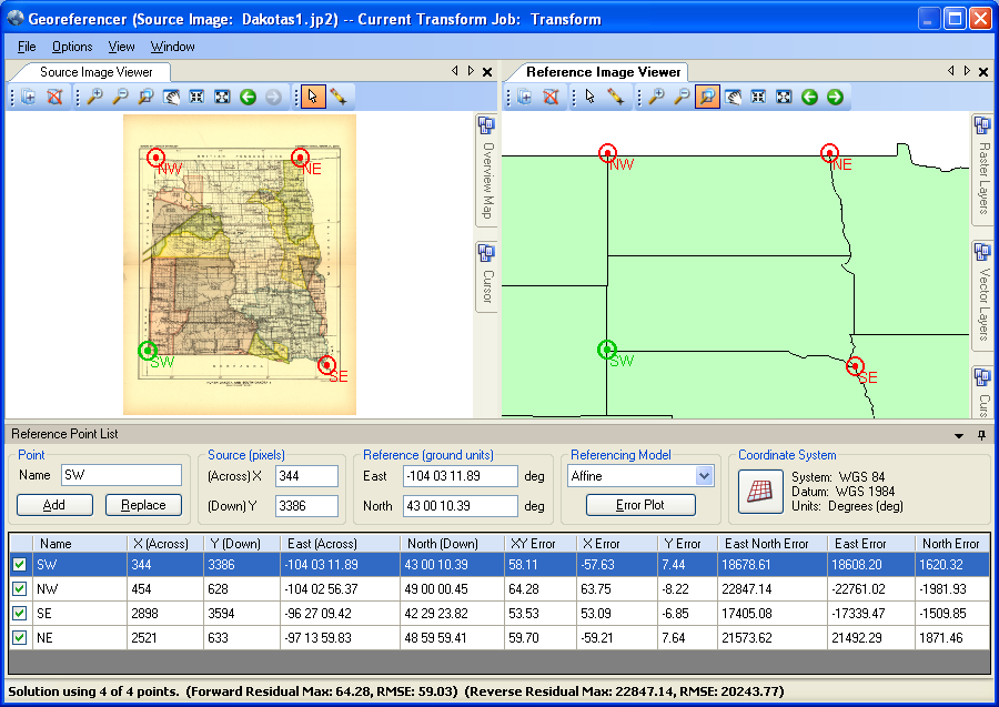
Geographic Transformer's Georeferencer
GeoTransform
Features
GeoTransform is a fully object-oriented Class Library for software developers.
Powerful, reliable, accurate and fast!
It couldn't be simpler to use the industry leading reprojection and transformation tool. Just think of the cost and hassle of reinventing the wheel! GeoTransform is a fully object-oriented Class Library for software programmers using Visual Studio and other Windows development tools that will save your company time-to-market and production costs.
Transformation Methods
Affine (minimum three points)
1st Order Polynomial (minimum four points)
2nd Order Polynomial (minimum six points)
3rd Order Polynomial (minimum ten points)
4th Order Polynomial (minimum fifteen points)
5th Order Polynomial (minimum twenty-one points)
Enables accurate and powerful raster format, reprojection and resampling support
Improved coordinate system reading and writing for ESRI and ERMapper coordinate system definitions.
New interoperability components allow sharing data between GeoTransform and GeoCalc applications.
Includes image resampling methods such as nearest neighbor, bilinear interpolation, and cubic convolution.
Create referencing, raster transformation, reprojection, image tiling, mosaicking and compression in your application.
Enhanced clipping code allows you to manage, manipulate, and process large datasets like never before.
Raster rendering to a standard Window handle for supported formats.
Reprojection
GeoTransform features the unmatched geodetic datasource of GeoCalc.XML. You can even define your own custom units, ellipsoids, datums and coordinate systems.
Specifically:
Over 3500 pre-defined coordinate systems
Over 165 ellipsoids
Over 630 datum transformations
Over 70 linear units and much more
There is now also projection recovery technology to find lost projection information within your data.
Sample Code and Sample Applications
GeoTransform is embedded in our Geographic Transformer. If you are looking for feature/function ideas, download an evaluation copy of the Transformer. Sample code is available on the downloads section of our website under GeoTransform.
Programmatic capabilities
Reference file coordinate conversion on the reference file itself. Re-reference programmatically to convert the reference to a new coordinate system without doing a transform of the image.
Clip to polygon output write for Shape files. You can use a shape file to a define polygon area definition for the output of the raster transformation. These shape files must have only one polygon in it.
GeoTransform
Details
Image Resampling Methods
(Provides different methods for displaying pixel values in output image.)
(Image pixel to reference coordinate system transformation.)
Affine (minimum three points)
1st Order Polynomial (minimum four points)
2nd Order Polynomial (minimum six points)
3rd Order Polynomial (minimum ten points)
4th Order Polynomial (minimum fifteen points)
5th Order Polynomial (minimum twenty-one points)
Coordinate Conversion Parameters
We include a comprehensive coordinate conversion parameter database that contains most common coordinate systems in use throughout the world. You can completely customize this XML file by adding or removing parameters. Currently, the coordinate conversion database contains:
Over 3500 pre-defined coordinate systems
Over 1200 datum shifts
Over 400 horizontal datums
Over 80 various unit definitions
14 prime meridians
A dozen vertical datums
Common coordinate systems included:
US State Plane 1927 (both original and exact solutions)
US State Plane 1983
UTM (Universal Transverse Mercator) North and South zones
Gauss-Kruger Modified, 3TM, and 6TM
XYZ Cartesian Eath-Centered Earth Fixed (ECEF)
New Zealand Map Grid
Grids for Argentina, Australia, Austria, Bahrain, Belgium, Borneo, Columbia, Cuba, Egypt, England, France, Ghana, Greece, India, Iraq, Ireland, Italy, Japan, Minnesota, Netherlands, New Brunswick, New Zealand, Nigeria, Peru, Phillipines, Qatar, Quebec, Rumania, Veracruz, and many more. More are being added all the time!
Map Projections
Aitoff
Alaska 27
Albers Equal Area
Azimuthal Equal Area
Azimuthal Equidistant
Behrmann
Belgium 72
Bipolar Oblique Conformal Conic
Bonne
Cassini
Craster Parabolic
Danish System 34
Danish System 34 1999
Double Stereographic
Eckert I
Eckert II
Eckert III
Eckert IV
Eckert V
Eckert VI
Egyseges Orszagos Vetulet
Equal Area Cylindrical
Equidistant Conic
Equidistant Cylindrical
European Stereographic
Fuller
Gall Stereographic
Gnomic
Goode Homolosine
Guam 27
Hammer Aitoff
Hotine Oblique Mercator
Hotine Oblique Mercator 1pt
Hotine Oblique Mercator 1pt Method2
IMW Polyconic
Krovak
Laborde
Lambert 27
Lambert Conformal Conic
Lambert Conformal Conic Extended
Lambert Tangent
Loximuthal
McBryde Thomas Flat Polar Quartic
Mercator
Military Grid Reference System
Miller Cylindrical
Mollweide
Natural Earth
New Zealand Map Grid
Oblique Area Cylindrical
Oblique Mercator Azimuth
Oblique Mercator Two Points
Orthographic
Perspective Conic
Polar Azimuthal Equal Area
Polar Equidistant
Polar Stereographic
Polyconic
Quartic Authalic
Robinson
Sinusoidal
Space Oblique Mercator
Stereographic
Stereographic 70
Swiss Oblique Mercator
Tilted Perspective
Times
Transverse Mercator
Transverse Mercator 27
Transverse Mercator Extended
Transverse Mercator Snyder
Transverse Mercator South Oriented
Two Point Equidistant
Two Point Fit
Universal Transverse Mercator
Van Der Grinten
Van Der Grinten IV
V and H
Vertical Perspective
Winkel I
Winkel II
Winkel Tripel
Datum Transformations
Canadian National Transformation V2 (NTv2)
ED50 to ED87 North Sea
Four Parameter
Geocentric Translation
General Second Order Polynomial
General Third Order Polynomial
General Fourth Order Polynomial
General Fifth Order Polynomial
General Sixth Order Polynomial
Longitude Rotation
Madrid ED50 Polynomial Transformation
Molodensky
Molodensky-Badekas
DMA Multiple Regression Equations
Custom MRE
NADCON/HARN
NTF to RGF93 Grid Transformation
Ordnance Survey National Grid Transform of 2002
Seven Parameter CFR
Seven Parameter PVR
Six Parameter
Tokyo to JGD2000 Grid Transformation
Vertical Datum Transformations
Australian Geoid Model of 1998 - AUSGEOID98
Australian geoid model of 2009
Colombia Geoid Model of 2004 ? GEOCOL04
Danish vertical reference of 1990
Earth Geopotential Model of 1996 ? EGM96
Iberian Geoid Model of 1995
Iberian Gravimetric Model of 2005
Japanese GSI Geoid Model of 2000
Netherlands vertical model of 2004
Ordnance Survey Geoid Model of 2002 - OSGM02
OSU91A
Referent Altimetrique Corse 2009
Referent Altimetrique France Continentale 2009
South African Geoid Model of 2010
Swedish Geoid Model of 2008
United States Geoid Model of 1996 - GEOID96
United States Geoid Model of 1999 - GEOID99
United States Geoid Model of 2003 - GEOID03
Venezuelan Geoid Model of 2004
NAD27 to NAD83 Conversions
NAD27 to NAD83 conversions (or vice versa) with the United States and associated territories are performed using exactly the same algorithm and data files as used by the National Geodetic Service's NADCON program. Results are numerically identical to those of NADCON. Version 2.0 of the Canadian National Transformation is fully supported for conversion within Canada
NAD83 to HPGN Conversions
NAD83 to HPGN (NAD83/91 or HARN) conversions (or vice versa) are performed using the exact same algorithm and data files used by, and results are numerically identical to, the National Geodetic Service's NADCON program.
Compatibility
ArcView
ArcInfo
MapInfo
Microstation
AutoCAD support for R12, R13, R14, AutoCAD 2000/2002, AutoCAD 2004/2006 and AutoCAD 2007/2008
Q: How simple is it embed GeoTransform into my own application? A: Very simple. GeoTransform consists of two function calls:
BMgttp_Transform performs a transformation with values specified within the TRANSFORMSETTINGS structure.
BMgttmp_SetStatusCallback allows you to set a "callback hook" into the GeoTransform library. This callback hook allows your application to update the user interface during the transformation process.
The online help file provides numerous code examples.
Q: Can I use GeoTransform within my Visual Basic application? A: Yes. Many development tools for Microsoft Windows can make use of GeoMosaic, including Visual Basic, Visual C++, Borland C++, Symantec C++, Watcom C++, Microsoft FORTRAN, Borland Turbo Pascal, SQL Windows, Delphi, and others.
Q: What type of image referencing files can GeoTransform produce? A: GeoTransform supports all of the popular image referencing formats, including the ESRI World file (*.tfw, *.jgw, and *.wld), MapInfo Table (*.tab), and the Blue Marble Reference Settings file (*.rsf). GeoTransform can be used to produce all three types for a single image during the transformation process.
Q: I need my application to tile raster images during the transformation process. Does GeoTransform support this functionality? A: Yes. The GeoTransform component will tile images "on the fly" during the transformation process. Two types of tiling schemes are supported: 1.5 section and Row and Column. The tile height and width can be specified as well. For example, the property dRowColOriginN defines the coordinate value in destination image coordinates relative to a geographic Origin. This coordinate and the dTileHeight and dTileWidth parameters will determine the extents of the tiles and therefore the files created in the Tiling. The tile origin must be established to the north and east of the northeast corner of the area to be tiled according to the Row and Column scheme.
Q: What is the format of the Blue Marble referencing file (.RSF)? A: The first line contains the version of the file format, not to be confused with the version of the software, and the total number of points in the file. The remaining lines contain, in each line, the point ID, the x (row) pixel, the y (column) pixel, the z (elevation) value which is usually 0.00 followed by the ground coordinates expressed as Latitude or Northing (Y), Longitude or Easting (X) and Elevation (Z). The last value indicates whether the point described on that line is included in the solution, 0 = not included and 1 = included. Here is an example:


 Geographic Transformer's Georeferencer
