
필요한 최적의 소프트웨어와 컨설팅을
공급하도록 노력하겠습니다.


|
What's new |
|
|
2008년 10월에 출시된 3D-Doctor의 새로운 기능들이번에 추가된 새로운 기능은 새로운 Interactive Image Slice Alignment Tool("Image/Align Slices") 기능입니다. 이 기능은 기존의 "Image Alignment by Markers" 툴을 대체합니다. The commands under the Image/Align Slices submenu allow you to move or rotate image slice around until it is aligned to the neighbor slice.
The image slice alignment should be done first before doing segmentation, 3D rendering or other processing.
The following steps explain how to use the Align Slices commands to align the slices of a multi-plane image: 1. Open the image stack using the File/Open command. You should see two windows, the image plane window and the montage window. If you have not created an image stack list, you can use the “New Stack” command to do so. 2. Select Image/Align Slices/Start Alignment to start the alignment tool. The current image slice is turned transparent and displayed on top of the previous slice. For example, if your current image plane is 55, then image plane 54 is displayed together with 55. Both are displayed transparent. The initial tool is “Move Slice”. Hold down the left mouse button and move the cursor within the image window to move the current image slice around until it is properly aligned with the previous slice. 3. If you need to rotate the image slice, click the right mouse button to bring up the floating popup menu. Select the “Rotate Slice” tool. To rotate the slice, simply hold down the left mouse button and move within the image to rotate. Once the image slice is aligned, release the left mouse button to confirm. 4. Use the F5 and F6 function keys to move to the previous and next plane to continue the alignment process. Repeat Step 2 and 3 to align all image slices. Even though the slices appear to be aligned at this point, the alignment is for display only and the current image stack is not changed. You'll need to follow the next step to save the aligned image stack to a new file for further processing. 5. Once all slices are properly aligned, click the right mouse button to bring up the popup menu and select the “Save Aligned Image” command to save the results to a new image file. The Save As dialog box will appear and you can enter the file name that is going to be used to store the new aligned image. Click the “OK” button to start the alignment process. When the process is finished, use the File/Open command to open the aligned image file for display and processing. The current image stack is not changed during the process.
|
2008년 5월에 출시된 3D-Doctor의 새로운 기능들1. A new "Add Folder" option is added to the “New Stack” command. This function will search all files and subfolders within the selected folder for image files and add them to a stack list. It solves the problem where some CT scanners save DICOM files in many subfolders. 2. A new 3D angle measurement tool is added to the surface rendering window. Select “Tool/Measure Angle” to start the tool. Click 3 points on a model to get the angle measured. 3. New “Image/Tilt Correction” function is implemented to correct gantry tilt image distortion. Some CT image slices (most are in DICOM format) are acquired with a tilted gantry so the slices are not perfectly perpendicular to the main axis. This new function will use the angle stored in the DICOM header to compensate the tilt and generate image slices that are perpendicular to the main axis for segmentation and 3D rendering applications. 4. Added “Line Width” attribute for the object boundary display. To change the boundary line display width, use the “Edit/Object Settings” command and then click on the “Line Type” button. 5. Enabled editing options for the regions of interest (ROI) created from object boundaries (using the “Edit/ROI/ROI from Boundaries command). ROIs on different image planes can be edited and deleted using the ROI editor. 6. Added the “Move Note” function to the “Annotation Editor” to move an existing annotation to a different location. 7. The “Delete Node” tool under the “Boundary Editor” has been improved to allow removing nodes continuously. When the “Delete Node” tool is selected, pressing down the left mouse button will change the tool to a node eraser and boundary nodes touched by the eraser will be removed. 8. Improved the "Copy Boundary" tool under the “Boundary Editor”. One can draw a selection rectangle to select a group of boundaries and then use the “Control-C” key to copy. The boundaries can be pasted to a different image plane using the “Paste” or “Control-V” key. 9. Additional image output file formats are added to the “File/Save Window” command. The window image can now be saved to BMP, TIFF, JPEG, DICOM and other formats. 10. The 3D “Volume and Surface Area Calculation” command now uses an area-weighted algorithm to calculate the centroid of a 3D object. 11. HTML based online help is now supported in 3D-DOCTOR. New image conversion function to convert 1-bit image to 8-bit grayscale. New Region Growing Based Segmentation (Nov. 2007)This new version includes the following new functions and improvements: 1. New region growing based segmentation algorithm is implemented for the “Segment Object” command. The new algorithm segments more effectively for soft and tumor tissues by using both texture and edge information from the image. 이 기능에 대한 비디오 가이드를 보기 원하시면 여기를 클릭하십시오. 2. The image reslicing functions (Reslicing X/Y) is updated to use a multi-pass algorithm to reduce the system memory usage to handle large size image stack. 3. Updated the image saving and exporting functions to use sequential filenames for image slices. 4. Added the "Notes" function so notes and annotations can be added to the surface file. 5. Some other bug fixes and minor updates, including a STL file import issue with incorrect object display location.
|
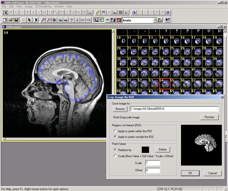
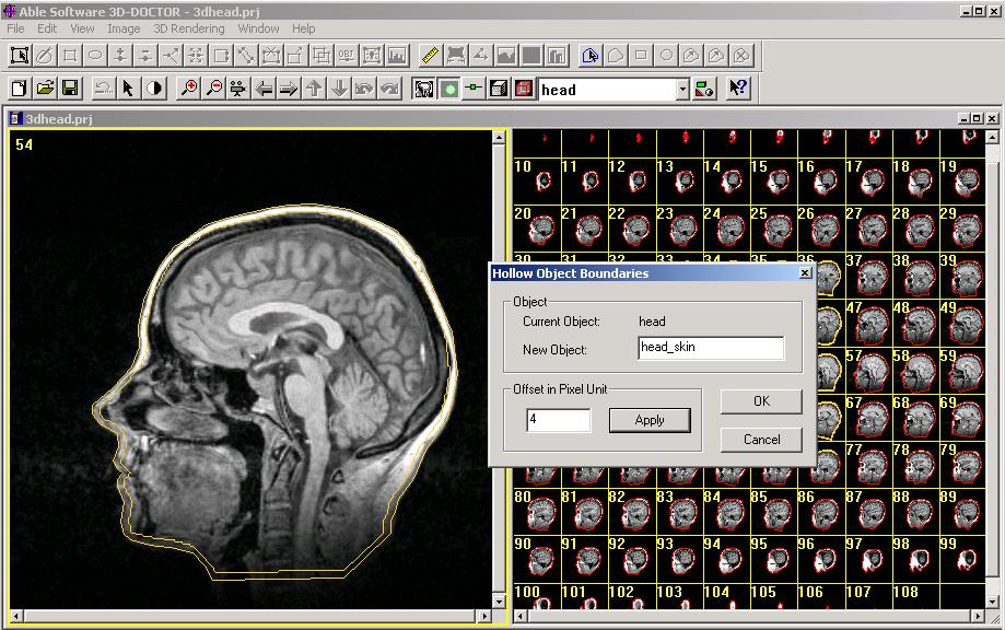
New Image Cropping and Creating Hollow Object (Dec. 2006)
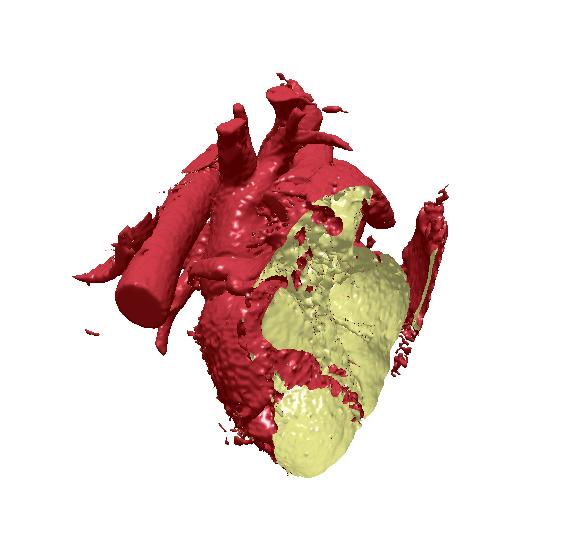
This new version includes the following new functions and improvements: New Functions for Splitting 3D Objects (Nov. 2006)A new release of 3D-DOCTOR is now available at our website for download. This new version includes the following new functions, user interface improvements and updates:
3D-DOCTOR Adds New Functions for Image Import(Sept. 2006) This new version includes the following new functions, user interface improvements and updates: Display and Printing
Image File Handling
Boundary Editor A new option to move a group of boundaries within a selection rectangle is implemented in the Boundary Editor. To move a group of boundaries, start the “Boundary Editor” and switch to the “Move Boundary” mode. Hold down the SHIFT-key and the LEFT mouse button to draw a selection rectangle around the boundaries to be moved, then hold down the LEFT mouse button to move.
New Functions for 3D Model, Boundary and DICOM Support
(March 2006) This new version includes the following new functions, user interface improvements and updates:
Interactive 3D Image Registration and Enhanced Volume Rendering (Feb. 2006)This new version includes the following new functions, user interface improvements and updates:
[2005년 11월] 2005년 11월에 업그레이드된 주요 기능은 다음과 같습니다.
1. 슬라이스들(Slices)의 범위를 선택하는 새로운 기능을 볼륨 렌더링에 활용할 수 있게 되었습니다. 일단 볼륨 렌더링이 만들어지면, "View/Slice Range"를 이용하여 선택코자하는 범위를 입력할 수 있습니다. 이 기능을 이용하면 볼륨내의 특정 부분만 렌더링할 수 있습니다. 2. 슬라이스들을 보이게 하거나 감출 수 있는 기능 추가 - "View/Slices/Hide Slices" 또는 "Show Slices" 기능을 이용하여 볼륨의 앞쪽 또는 뒤쪽에서 슬라이들을 감추거나 표시할 수 있습니다. "Front to Back" 명령을 이용하여 방위(Orientation)를 설정할 수 있습니다. 이것이 체크되었을 때 볼륨 앞쪽의 슬라이스들이 방위에 사용됩니다. 3. "View/All Slices" 명령 - 볼륨 렌더링에 사용할 모든 슬라이스들의 선택을 재설정(reset)합니다. 4. 확대/축소(Zooming in and out) 제어를 위해 휠 마우스를 사용할 수 있습니다.
1. "Object Animation" 기능 추가 - 이 기능은 에니메이션 시퀀스를 만들어 에니메이션을 하는 동안 선택된 오브젝트들을 감추가나 나타나게 할 수 있습니다. 2. 새로운 원근 투영 기법으로 3D 서페이스 모델 디스플레이를 개선하였습니다. 3. 볼륨 렌더링에서와 마찬가지로 확대/축소를 할 때 휠 마우스를 사용할 수 있게 되었습니다.
1. "All Views" 명령을 활용할 때, "View/Full Resolution"이란 새로운 기능을 이용하여 측면과 앞쪽에 최대 해상도(full resolution)을 생성할 수 있습니다. 2. "Flip Vertical" 기능 추가 - 측면 보기의 상하 방위를 반전 시킬 수 있습니다. 3. 3D Wizard를 개선하여 프로세싱 상태를 보다 잘 표현하도록 하였습니다. 4. Image Planes에서의 스크롤을 할 때 휠 마우스를 사용할 수 있게 되었습니다. 5. "Segment Object"에 사용된 알고리즘을 개선하여 보다 뛰어난 영상 분할 작업을 할 수 있습니다.
1. 3D-Doctor에서 출력한 DICOM 파일에 DICOM 태그(tag)를 추가하여 다른 프로그램과 보다 호환이 잘 될 수 있도록 하였습니다. 영상 리스트(Stack list) 또는 3D TIFF 파일을 출력하기 위하여, 단순히 "File/Save Image AS(다른 이름으로 저장하기)" 기능을 활용하시면 됩니다. 그리고, 파일 확장자명이 ".DCM"인지 확인하시고 "All Planes"를 선택하여 모든 영상을 저장하시거나 일부만 선택하여 저장하십시오. 이전 버전에서 저장해둔 DICOM 파일의 경우, Stack List를 읽어들인 후 "Save Image As" 버튼을 눌러 새롭게 DICOM 파일로 저장하십시오. 그러면, 태그가 추가됩니다. 2. "New Stack" 명령에 "Split Image Series"란 새로운 옵션이 추가되어 일부 이미지에 대해 선택/해제를 하여 읽을 수 있습니다. 이 기능은 하나의 이미지 셑에 여러 시리즈로 저장된 DICOM 파일들을 다룰 때 유용합니다. 3. "New Stack" 명령에서 폴더의 이름을 기본 Stack list 파일로 사용할 수 있습니다. 4. 3D VRML 출력 기능을 개선하여 호환성을 높였습니다.
"Full Frames(Uncompressed)"를 이용하여 에니메이션을 인코딩하게 되면, 매우 큰 동영상 파일(AVI)을 얻게 되는데, 파일의 크기를 줄일 수 있는 몇가지 방법을 소개합니다. 1. 에니메이션을 시작하기전에 윈도우의 크기를 줄이십시오. 윈도우가 작을 수록 파일의 용량도 작아집니다. 2. 압축 기반의 인코딩을 사용하십시오. 예를들면, "Microsoft Video 1"을 이용한 인코딩은 파일의 크기를 상당히 줄여줍니다. 그러나, 해당 SW가 여러분의 컴퓨터에 설치되어 있는지 미리 확인하십시오.(설치되어 있지 않다면 당연히 이 기능을 활용할 수 없습니다.) 이외에 3D-Doctor에 추가되었으면 하는 기능이나 개선되기를 희망하는 부분이 있다면 언제든지 저희 회사로 연락 주십시오. 요구하시는 기능들이 추후 버전에서 반영되도록 최선을 다하겠습니다.
[2005년 10월] 2005년 10월에 업그레이드된 주요 기능은 다음과 같습니다.
1. 스킨(Skin) 표현을 위해 텍스쳐 이미지를 3D 서페이스 렌더링에 사용할 수 있는 기능 추가 이 기능을 이용하면, 실제 조직의 텍스쳐(Texture) 영상을 이용하여 보다 현실감있는 렌더링을 할 수 있습니다. 이 텍스쳐 디스플레이 기능을 이용하기 이하여, 먼저 해당 영상을 찾아 필요한 일부를 잘라서 JPEG이나 BMP 파일로 저장 하십시오. Surface 렌더링 윈도우에서 "View/Object" 명령을 실행하십시오. 다이얼로 박스가 나타나면, 한 오브젝트를 선택하신 후 "Texture"버튼을 클릭하십시오. 그러면, 텍스쳐 이미지 파일을 선택하여 불러 오도록 요청 받게 됩니다. 영상이 읽혀지면, 디스플레이에 자동으로 적용되어 나타나게 됩니다. 만약 여러분 모델이 매우 많은 삼각망으로 구성되어 있다면, 다소 시간이 걸릴 수도 있습니다. 또한, 보다 작은 텍스쳐 이미지가 성능에 도움이 됩니다. 각각의 오브젝트에 대해 텍스쳐 사용 여부(On/Off)를 설정할 수 있습니다. 2. Surface 렌더링할 때 색상과 모델 조명 기능 개선 - 오브젝트 칼라 속성 조절을 위한 슬라이더 바에 "Pick Color" 버튼이 추가되었습니다. 3. "Split Object" 또는 "Crop Object" 명령을 이용하여 특정 모델을 떼어내거나 잘라낸 후에, 뒤에 있는 Surface를 볼 수 있고 디스플레이할 수 있습니다. 4. 3D 회전을 다루는 기능이 개선됨 - 왼쪽 마우스 버튼으로 드래그할 때 3D 회전을 부드럽게하는 새로운 알고리즘이 적용되었습니다. 오른쪽 마우스 버튼은 줌인/줌아웃(확대/축소) 기능을 제어합니다. 5. Surface 모델위에서 왼쪽 마우스 버튼을 누르면, 이미지 plane 수를 자동으로 디스플레이 합니다. 이 기능은 Surface의 불규칙성 및 위치를 보다 쉽게 체크할 수 있게 합니다. 6. "Tools" 메뉴에 "Clear Measure"라는 새로운 기능이 추가되었습니다. 이 기능은 새로운 측정을 시작하기 전에 현재 입력된 측정 라인들을 제거합니다. "ESC" 키를 이용하여 이 기능을 수행할 수도 있습니다.
1. "View"메뉴 아래에 "Lighting"이라는 새로운 기능이 추가되었습니다. 이 기능은 조명 효과의 On/Off를 조절합니다. 2. "Direct Volume Rendering" 기능을 위한 ROIs(Regions of Interest, 관심영역) 기능을 활용할 수 있습니다.
1. STL ASCII 출력 기능이 개선되어 출력된 파일은 다른 소프트웨어 패키지와의 호환성이 더욱 좋아졌습니다. 2. "Contrast Adjustment" 인터페이스 기능이 개선됨 - "Previous" 버튼을 눌러 이전의 설정들을 복구할 수 있습니다. 3. "Object Report"에 볼륨 계산 기능을 추가 - 이 기능은 오브젝트안의 총 복셀수와 "Calibration"기능에서 정의한 복셀의 크기를 이용하여 계산합니다. 4. "Create Movie" 명령으로 동영상(AVI) 파일을 만들 때 영상 캡쳐시 윈도우 경계선과 스크롤 바를 제거하였습니다. 5.일본어 및 중국어 사용자 인터페이스 지원 - 사용하는 Windows가 중국 또는 일본어 버전인 경우 중국 또는 일본어 사용자 인터페이스를 자동으로 표시해 줍니다.
[2005년 4월] 금번에 업그레이드된 3D-Doctor는 사용자 인터페이스를 개선하여 사용의 편의성을 더욱 높였고 아래와 같은 기능들을 추가 및 업그레이드 하였습니다.
(1) Grayscale with Opaque Voxels : 영상 복셀들은 그레이스케일 값을 이용하여 그려지고, 음영이 만들어진 불투명체 및 ray로 다루어집니다. (2) Grayscale with Transparent Voxels : 복셀들은 3D 렌더링을 만들기 위한 투명체 및 Ray로 취급됩니다. (3) Color with Opaque Voxels : 칼라 쉐이딩(Shading)이 볼륨 렌더링에서 불투명 복셀에 적용됩니다. (4) Color with Transparent Voxels : 모든 복셀들이 레이 트레이싱(Ray Tracing) 처리에서 투명하게 다루어지며, 칼라 쉐이딩이 적용됩니다. 칼라는 인터랙티브하게 바꿀 수 있습니다. 여기를 클릭하시면 볼륨 렌더링 이미지 샘플들을 보실 수 있습니다. 이전의 볼륨 렌더링은 "Direct Volume"라는 이름으로 바뀌었고, 기능 자체는 바뀌지 않았습니다.
|
 Volume
Rendering(볼륨 렌더링)
Volume
Rendering(볼륨 렌더링)